04-Expansion_Pins
Expansion Pins
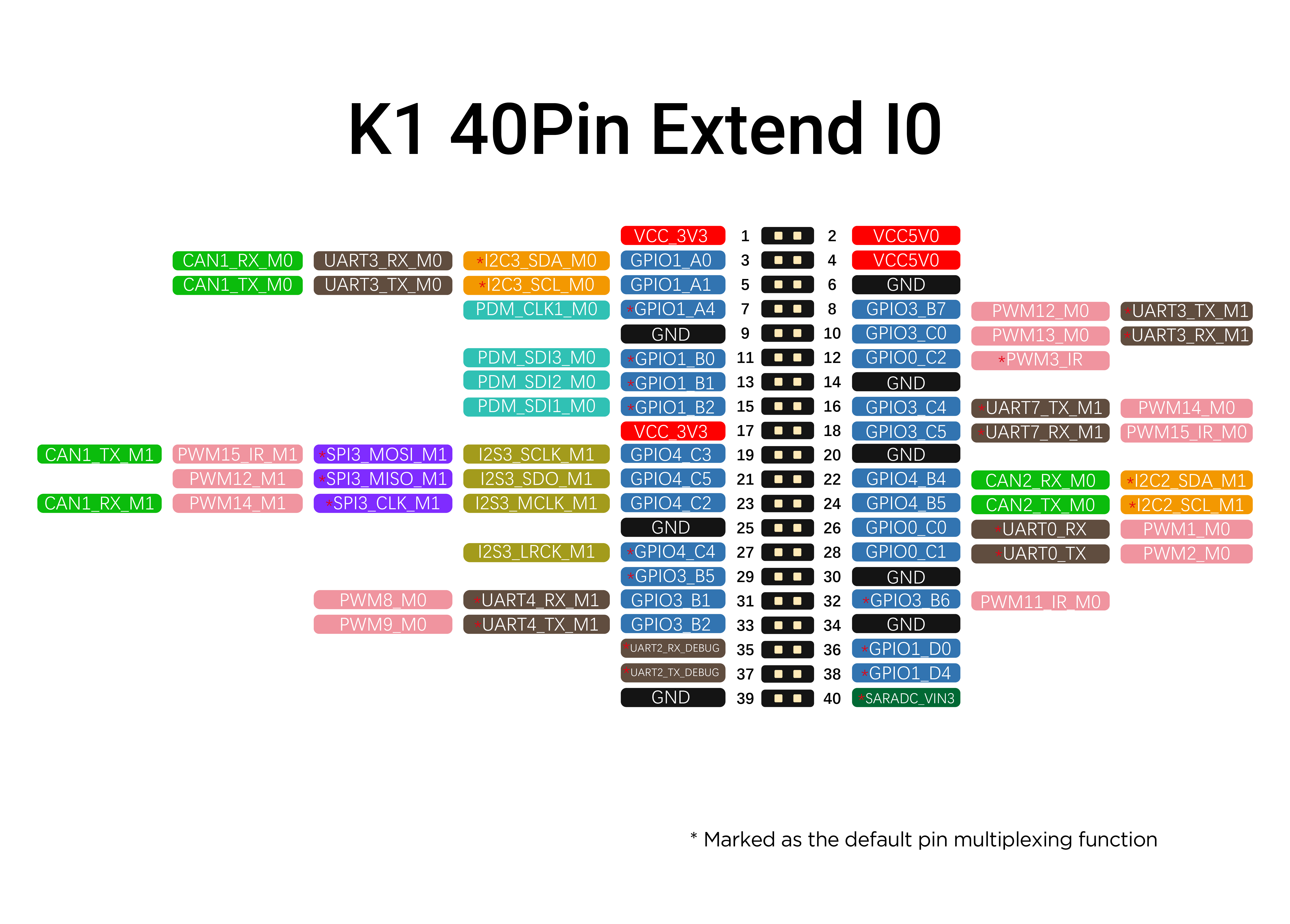
K1 Pin List

K1B Pin List

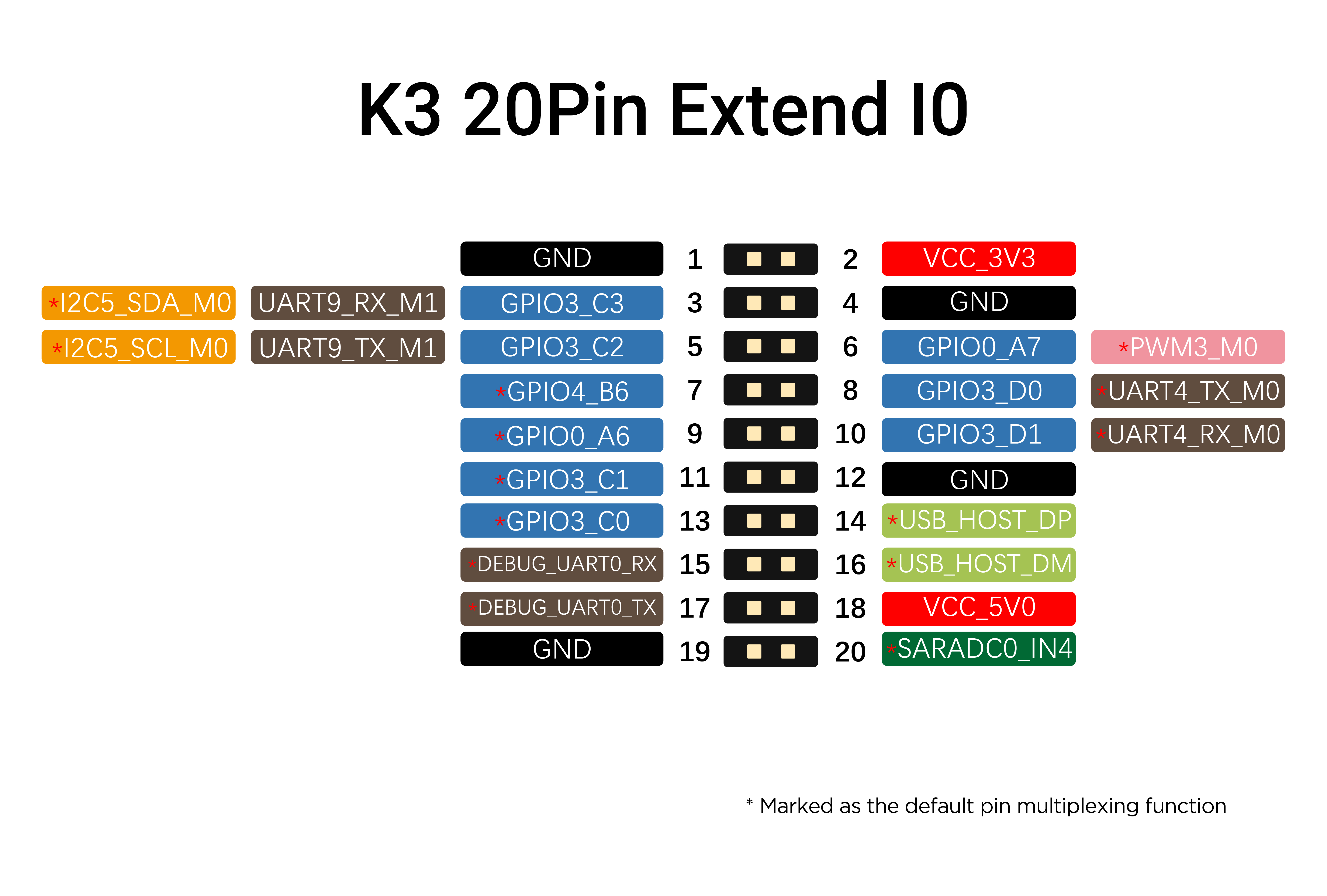
K3 Pin List

K8 Pin List

GPIO
Multiple controllable GPIOs are configured by default in the expansion pins of the development board.
First, confirm the location and number of the GPIO pins through the Expansion Pins section. You can control the state of the specified GPIO by referring to the following steps.
User-level Control of GPIO Level
GPIOs configured in the default software expansion pins are generally registered for this type of control.
This method can control the pin to output a high or low level.
View the GPIO registration list
Control GPIO via the command line
UART
One or more UARTs are generally configured by default in the expansion pins of each series of boards. After connecting the corresponding UART to be used, you can perform tests as follows.
Confirm the serial port number to be used
Check if the corresponding node exists
For example, UART4 corresponds to /dev/ttyS4
Perform a communication test using microcom
Android has microcom installed by default.
If the node found for serial port 4 is /dev/ttyS4
-s sets the baud rate to 115200
Verify using minicom:
It is recommended to use minicom on Linux.
Configuration is required for the first installation:
Use
minicom -sto turn offSerial port setup >> F Hardware Flow Control.Press the Esc key or Enter to return to the previous level and select
Save setup as dflto save.Select
Exit from Minicomto exit.
Use the following command:
Default display: The received content will be printed, and the sent content will not be printed.
Press
Ctrl+Ato enter the control mode for commands from B to Z. PressZfor help.
Ctrl+A W
Enable/disable auto line feed (disabled by default)
Ctrl+A E
Enable/disable input display (disabled by default)
Ctrl+A C
Clear the screen
Alternatively, use echo to send data directly
PWM
The RK3568 has 4 PWM modules, and each PWM module has 4 channels of PWM, totaling 16 channels of PWM.
User-level Configuration of PWM Output
The Extend 40Pin interface includes multiple channels of PWM. Taking the PWM3 channel as an example, enter the PWM configuration according to the following commands.
After successfully setting the configuration parameters as shown in the example, you can use a multimeter to measure the PWM3 pin, and the correct voltage should be around 1.6V.
Example: Set the PWM3 channel with a period of 10000ns, a duty cycle of 5000ns, and a polarity of normal.
The PWM path is /sys/class/pwm, and pwmchip* is numbered starting from 0 according to the enabling order. The following shows the settings for pwmchip0:
How to confirm the PWM corresponding to
pwmchip
fd8b0010.pwmis the corresponding node in the DTS.
ADC
The expansion pins of the mainboard are equipped with ADC. You can view the corresponding ADC position and channel number through the Expansion Pins section.
The following uses SARADC_VIN3 as an example for illustration.
Read the ADC value
Example:
Read the voltage value of channel 3
CAN
Applicable platforms: RK3568 / RK3576 / RK3588
Some RK chips support native CAN interfaces, which are usually led out to the expansion pins. The specific location can be found in the expansion pins section.
The native CAN interface of the chip cannot be used directly; an external level conversion circuit needs to be added.
Query the current network devices
CANFD Configuration
Turn off the CAN
Set the bit rate to 500KHz
Print the information of can0
Turn on the CAN
CAN FD Transmission
Transmit (standard frame, data frame, ID: 123, data: DEADBEEF):
Transmit (standard frame, remote frame, ID: 123)
CAN Reception
Turn on printing and wait for reception
Loopback Mode Test
Method 1:
After turning on the CAN, enter the following command to start the loopback self-test (the base address is configured according to the actual CAN started in the DTS).
0xfea60000is the DTS node of K8 CAN0.
In loopback mode, candump can receive data after cansend.
Example
Terminal 1
Start the loopback mode test and monitor the CAN
Terminal 2
Send the command
Method 2:
Start the loopback test
Run candump in the background and turn on printing
Send the command
SPI
Tool Location
Compilation
Select the
CROSS_COMPILEused by the kernel.
Loopback Mode Test
The main controller acts as the Master.
Short-circuit the MISO and MOSI pins.
Example
Last updated