# 04-Expansion\_Pins\_Testing
This document is used for users to quickly use or test the expansion pin functions of the motherboard.
## Symbol Explanation
* `SDK$`: Refers to the source code path.
* `console$`: Generally refers to the command-line console of the motherboard. [Motherboard command-line console](/kickpi-book/rk3576/en/02-getting_started_guide/02-quick_start_guide.md#console_readme)
* `ADB$`: Android Debug Bridge command-line tool, generally refers to an environment where ADB can be run.
## Expansion Pins
The development board is equipped with on-board expansion pin functions.
* It can be used to connect external devices (such as temperature sensors, humidity sensors, etc.).
* Communicate with other circuit boards or modules (I2C, SPI, UART, etc.).
* Customize GPIO functions.
For specific function expansion details, refer to the pin list.
The pin list marks the default configuration of each pin (marked with an asterisk) and provides the available alternative configurations for that pin.
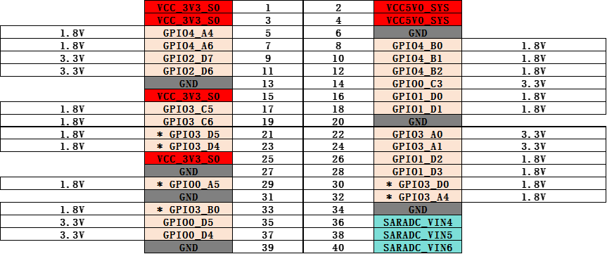
**K7 Expansion Pin List**

**K7 Pin Voltage**
## GPIO
The expansion pins of the K7 motherboard can be configured as GPIO pins. Check the corresponding GPIO pin positions and numbers in the [Expansion Pins section](#ExpansionPin-K7).
The default GPIO pins (marked with an asterisk) of the expansion pins are configured as output ports, which can control the GPIO to output high or low levels.
**List the registered GPIO control nodes**
```
console$ ls /sys/class/leds/
GPIO0_A5 GPIO3_B0 GPIO3_D4 GPIO3_D5 PCIE_PWREN SDMMC0_PWREN fan mmc2:: work
```
> To control the level state of the GPIO below, $GPIO needs to correspond to the listed GPIO names.
**Control the output level state of the GPIO**
Control the GPIO to output a high level
```
console$ echo 1 > /sys/class/leds/$GPIO/brightness
```
Control the GPIO to output a low level
```
console$ echo 0 > /sys/class/leds/$GPIO/brightness
```
Example:
Control GPIO3\_D4 to output a high level
```
console$ echo 1 > /sys/class/leds/GPIO3_D4/brightness
```
Control GPIO3\_D4 to output a low level
```
console$ echo 0 > /sys/class/leds/GPIO3_D4/brightness
```
## CAN
The expansion pins of the K7 motherboard can be configured as CAN interfaces. Check the corresponding CAN interface positions and numbers in the [Expansion Pins section](#ExpansionPin-K7).
**Query the current CAN device**
The following uses CAN0 as an example for illustration.
```
console$ ifconfig -a
...
can0 Link encap:UNSPEC Driver rk3576_canfd
NOARP MTU:16 Metric:1
RX packets:0 errors:0 dropped:0 overruns:0 frame:0
TX packets:0 errors:0 dropped:0 overruns:0 carrier:0
collisions:0 txqueuelen:10
RX bytes:0 TX bytes:0
Interrupt:63
...
```
> It can be seen that the device name is can0.
**Configure CAN**
Turn off CAN
```
console$ ip link set can0 down
```
Set the arbitration segment to a 1M baud rate and the data segment to a 3M baud rate
```
console$ ip link set can0 type can bitrate 1000000 dbitrate 3000000 fd on
```
View the configuration information of can0
```
console$ ip -details link show can0
```
Start CAN
```
console$ ip link set can0 up
```
**CAN Transmission**
Transmit (standard frame, data frame, ID: 123, data: DEADBEEF)
```
console$ cansend can0 123#DEADBEEF
```
Transmit (extended frame, data frame, ID: 00000123, data: DEADBEEF)
```
console$ cansend can0 00000123##1DEADBEEF
```
**CAN Reception**
Enable printing and wait for reception
```
console$ candump can0
```
**Loopback Mode Test**
```
console$ ip link set can0 down
console$ ip link set can0 type can bitrate 500000 sample-point 0.8 dbitrate 2000000 sample-point 0.8 fd on loopback on
console$ ip -details -statistics link show can0
console$ ip link set can0 up
console$ echo 4096 > /sys/class/net/can0/tx_queue_len
console$ candump can0 &
console$ cansend can0 00000123##1DEADBEEF
can0 00000123 [04] DE AD BE EF
```
> In loopback mode, the data sent by cansend can be received by candump.
## PWM
The expansion pins of the K7 motherboard can be configured as PWM interfaces. Check the corresponding PWM positions and channel numbers in the [Expansion Pins section](#ExpansionPin-K7).
**List the PWM nodes**
```
console$ ls /sys/class/pwm/
pwmchip0 pwmchip1 pwmchip2
```
**List the corresponding PWM DTS nodes**
```
console$ cat /sys/class/pwm/pwmchip*/device/uevent | grep FULLNAME
OF_FULLNAME=/pwm@27331000
OF_FULLNAME=/pwm@2ade6000
OF_FULLNAME=/pwm@2ade7000
```
> The corresponding relationships are as follows, from top to bottom, corresponding to pwmchip0 to pwmchip2.
>
> **PWM0\_CH1\_M0** - pwm0\_2ch\_1 - pwm\@27331000 - **pwmchip0**
>
> **PWM2\_CH6\_M2** - pwm2\_8ch\_6 - pwm\@2ade6000 - **pwmchip1**
>
> **PWM2\_CH7\_M2** - pwm2\_8ch\_7 - pwm\@2ade7000 - **pwmchip2**
**Configure PWM**
Example:
The software has already configured PWM0\_CH1\_M0 (marked with an asterisk) by default. The following uses PWM0\_CH1\_M0 for illustration.
Set the PWM0\_CH1\_M0 channel, corresponding to pwmchip0, with a period of 10000ns, a duty cycle of 5000ns, and a polarity of normal.
```
console$ echo 0 > /sys/class/pwm/pwmchip0/export
console$ echo 10000 > /sys/class/pwm/pwmchip0/pwm0/period
console$ echo 5000 > /sys/class/pwm/pwmchip0/pwm0/duty_cycle
console$ echo normal > /sys/class/pwm/pwmchip0/pwm0/polarity
console$ echo 1 > /sys/class/pwm/pwmchip0/pwm0/enable
```
> After successful configuration, you can use a multimeter to measure the PWM0\_CH1\_M0 pin, and the voltage should be around 1.6V.
## UART
The expansion pins of the K7 motherboard can be configured as UART interfaces. Check the corresponding UART positions and channel numbers in the [Expansion Pins section](#ExpansionPin-K7).
**Loopback Test**
The software has already configured UART8 by default. The following uses UART8 as an example for illustration.
Short-circuit RX and TX hardware.
Use microcom to specify UART8 for communication
```
console$ microcom -s 115200 /dev/ttyS8
```
Example:
```
root@linaro-alip:/# microcom -s 115200 -p /dev/ttyS8
[ 4218.137343] of_dma_request_slave_channel: dma-names property of node '/serial@2adb0000' missing or empty
connected to /dev/ttyS8
[ 4218.137431] dw-apb-uart 2adb0000.serial: failed to request DMA, use interrupt mode
Escape character: Ctrl-\
Type the escape character to get to the prompt.
hello uart word!
```
> In the loopback test, microcom can receive the output characters simultaneously.
## SPI
The expansion pins of the K7 motherboard can be configured as SPI interfaces. Check the corresponding SPI positions and channel numbers in the [Expansion Pins section](#ExpansionPin-K7).
**Loopback Test**
The software has already configured SPI4 by default. The following uses SPI4 as an example for illustration.
Short-circuit MISO and MOSI hardware.

List the SPI device nodes
```
console$ ls /dev/spi*
/dev/spidev4.0
```
Specify the device for testing
```
console$ spidev_test -D /dev/spidev4.0 -v -l -p "hello"
```
Example:
```
root@linaro-alip:/# ./spidev_test -D /dev/spidev4.0 -v -l -p "hello"
spi mode: 0x20
bits per word: 8
max speed: 500000 Hz (500 kHz)
TX | 68 65 6C 6C 6F __ __ __ __ __ __ __ __ __ __ __ __ __ __ __ __ __ __ __ __ __ __ __ __ __ __ |hello|
RX | 68 65 6C 6C 6F __ __ __ __ __ __ __ __ __ __ __ __ __ __ __ __ __ __ __ __ __ __ __ __ __ __ |hello|
```
> The tool's network disk path
>
> 3-SoftwareData\Linux\_Spi\_Tool\spidev\_test
## ADC
The expansion pins of the K7 motherboard are equipped with three ADC channels. Check the corresponding ADC positions and channel numbers in the [Expansion Pins section](#ExpansionPin-K7).
**Read the ADC value**
```
console$ cat /sys/bus/iio/devices/iio\:device0/in_voltage*_raw
```
Example:
Read the voltage value of channel 4
```
console$ cat /sys/bus/iio/devices/iio\:device0/in_voltage4_raw
3528
```
---
# Agent Instructions: Querying This Documentation
If you need additional information that is not directly available in this page, you can query the documentation dynamically by asking a question.
Perform an HTTP GET request on the current page URL with the `ask` query parameter:
```
GET https://tanzhs-private-organization.gitbook.io/kickpi-book/rk3576/en/02-getting_started_guide/04-expansion_pins_testing.md?ask=
```
The question should be specific, self-contained, and written in natural language.
The response will contain a direct answer to the question and relevant excerpts and sources from the documentation.
Use this mechanism when the answer is not explicitly present in the current page, you need clarification or additional context, or you want to retrieve related documentation sections.