Kickpi-Book
  • KICKPI Document
  • K5/K5C(A133)
    • A133中文文档
      • 01-主板介绍
        • 01-KICKPI-K5硬件介绍
        • 02-KICKPI-K5C硬件介绍
      • 02-入门必读
        • 01-网盘目录说明
        • 02-快速使用
        • 03-功能测试
        • 04-扩展引脚
      • 03-镜像烧录
        • 01-获取镜像文件
        • 02-SD卡烧录
        • 02-USB线烧录
      • 04-SDK编译
        • 01-编译环境搭建
        • 02-LINUX_SDK源码编译
        • 03-ANDROID_SDK源码编译
      • 05-外设驱动
        • LCD功能调试
        • LRADC按键配置
      • 06-ANDROID系统定制
        • 01-Android常用系统定制
      • 07-LINUX系统定制
        • 02-Linux常用系统定制
      • 08-进阶
        • K5C主板供电
        • 安卓休眠唤醒
        • 13-硬件工厂测试
    • en
      • 01-Development_board_Introduction
        • 01-KICKPI-K5_Hardware_Introduction
        • 02-KICKPI-K5C_Hardware_Introduction
      • 02-Getting_Started_Guide
        • 01-KICKPI_Cloud_Storage_Introduction
        • 02-Quick_Start_Guide
        • 03-Functional_Testing
        • 04-Expansion_Pins_Testing
      • 03-Image_Flashing_Guide
        • 01-How_to_Get_Image_File
        • 02-SD Card Burning
        • 03-USB_Cable_Flashing
      • 04-SDK_Compilation_Guide
        • 01-Compilation_Environment_Setup
        • 02-Linux_SDK_Compilation
        • 03-Android_SDK_Compilation
      • 06-Android_System_Customization
        • 01-Android_Common_System_Customization
      • 07-Linux_System_Customization
        • ADB_Tutorial
  • K2B/K2C(H618)
    • en
      • 01-Development_board_Introduction
        • 01-KICKPI-K2B_Hardware_Introduction
        • 02-KICKPI-K2B_Hardware_Introduction
      • 02-Getting_Started_Guide
        • 01-KICKPI_Cloud_Storage_Introduction
        • 02-Quick_Start_Guide
        • 03-Functional_Testing
        • 04-Expansion_Pins_Testing
      • 03-Image_Flashing_Guide
        • 01-SD_Card_Flashing
        • 02-USB_Cable_Flashing
      • 04-SDK_Compilation_Guide
        • 01-Compilation_Environment_Setup
        • 02-Linux_SDK_Compilation
        • 03-Android_SDK_Compilation
      • 05-Drivers_Development
        • RTC
      • 06-Android_System_Customization
        • 01-Android_Common_System_Customization
      • 07-Linux_System_Customization
        • 01-Linux_Common_System_Customization
      • 08-Advanced_Topics
        • Hardware_Factory_Testing
        • Keybox
    • zh
      • 01-主板介绍
        • 01-KICKPI-K2B硬件介绍
        • 02-KICKPI-K2C硬件介绍
      • 02-入门必读
        • 01-网盘目录说明
        • 02-快速使用
        • 03-功能测试
        • 04-扩展引脚
      • 03-镜像烧录
        • 01-SD卡烧录
        • 02-USB线烧录
      • 04-SDK编译
        • 01-编译环境搭建
        • 02-LINUX_SDK源码编译
        • 2. Android SDK编译
      • 05-外设驱动
        • RTC
      • 06-Android系统定制
        • Android常用系统定制
      • 07-Linux系统定制
        • 01-Linux常用系统定制
        • 02-Linux_QT开发环境搭建
      • 08-进阶
        • Keybox
        • Secure Boot
        • Windows_QT开发环境搭建
        • 扩展引脚功能定制
        • 硬件工厂测试
  • K1/K1B/K3/K8(RK356x-RK3588)
    • en
      • 01-Development_board_Introduction
        • 01-RK_Chip_Comparison_Introduction
        • 02-KICKPI-K1_Hardware_Introduction
        • 03-KICKPI-K1B_Hardware_Introduction
        • 04-KICKPI-K3_Hardware_Introduction
        • 05-KICKPI-K8_Hardware_Introduction
      • 02-Getting_Started_Guide
        • 01-Cloud_Storage_Directory_Description
        • 02-K1-Quick_Start_Guide
        • 02-K1B-Quick_Start_Guide
        • 02-K3-Quick_Start_Guide
        • 02-K8-Quick_Start_Guide
        • 03-Functional_Testing
        • 04-Expansion_Pins
      • 03-Image_Flashing_Guide
        • 01-USB_Cable_Flashing
      • 04-SDK_Compilation_Guide
        • 01-Compilation_Environment_Setup
        • 02-LINUX_SDK_Compilation
        • 03-ANDROID_SDK_Compilation
      • 05-Drivers_Development
        • GPIO
        • Kernel
        • LCD
        • PWM
        • RTC
      • 06-Android_System_Customization
        • 01-Common_Android_System_Customizations
        • 01-Common_Android_System_Customizations
      • 07-Linux_System_Customization
        • 01-Common_Linux_System_Customization
        • 02-Installing_VNC_on_Linux
        • 03-Linux_Docker
        • 04-Linux_QT_Environment_Setup
        • 05-Linux_NPU_YOLOV5S_object_detection
      • 08-Advanced_Topics
        • 01-Hardware_Factory_Test
        • 02-Hardware_Aging_Test
        • 03-Firmware_Unpacking_and_Packing
    • zh
      • 01-主板介绍
        • 01-RK芯片对比介绍
        • 02-KICKPI-K1硬件介绍
        • 03-KICKPI-K1B硬件介绍
        • 04-KICKPI-K3硬件介绍
        • 05-KICKPI-K8硬件介绍
      • 02-入门必读
        • 01-网盘目录说明
        • 02-K1-快速使用
        • 02-K1B-快速使用
        • 02-K3-快速使用
        • 02-K8-快速使用
        • 03-功能测试
        • 04-拓展引脚
      • 03-镜像烧录
        • 01-获取镜像文件
        • 02-USB线烧录
      • 04-SDK编译
        • 01-编译环境搭建
        • 02-LINUX_SDK编译
        • 03-ANDROID_SDK编译
      • 05-外设驱动
        • GPIO
        • Kernel
        • LCD
        • PWM
        • RTC
      • 06-ANDROID系统定制
        • 01-Android常用系统定制
        • 07-Android NPU YOLOV5 目标检测
      • 07-LINUX系统定制
        • 01-Linux常用系统定制
        • 02-Linux安装VNC
        • 03-Linux Docker环境搭建
        • 04-Linux QT环境搭建
        • 05-Linux NPU YOLOV5S 目标检测
      • 08-进阶
        • 01-硬件工厂测试
        • 02-硬件老化测试
        • 03-固件解包和打包
  • K7(RK3576)
    • en
      • 01-Development_board_Introduction
        • 01-KICKPI-K7_Hardware_Introduction
      • 02-Getting_Started_Guide
        • 01-KICKPI_Cloud_Storage_Introduction
        • 02-Quick_Start_Guide
        • 03-Functional_Testing
        • 04-Expansion_Pins_Testing
      • 03-Image_Flashing_Guide
        • 01-How_to_Get_Image_File
        • 02-USB_Cable_Flashing
      • 04-SDK_Compilation_Guide
        • 01-Compilation_Environment_Setup
        • 02-Linux_SDK_Compilation
        • 03-Android_SDK_Compilation
      • 05-Drivers_Development
        • ADC
        • PWM
      • 06-Android_System_Customization
        • 01-Android_Common_System_Customization
      • 07-Linux_System_Customization
        • 01-Linux_Common_System_Customization
        • 02-Linux_Docker_Environment_Setup
        • 03-Linux_NPU_YOLOv5s_Object_Detection
        • 04-Linux_DeepSeek_Large_Model
        • 05-Linux_VNC_Remote_Control
      • 08-Advanced_Topics
        • Advanced_Testing
    • zh
      • 01-主板介绍
        • 01-KICKPI-K7硬件介绍
      • 02-入门必读
        • 01-网盘目录说明
        • 02-快速使用
        • 03-功能测试
        • 04-拓展引脚
      • 03-镜像烧录
        • 01-获取镜像文件
        • 02-USB线烧录
      • 04-SDK编译
        • 01-编译环境搭建
        • 02-Linux_SDK编译
        • 03-Android_SDK编译
      • 05-外设驱动
        • ADC
        • PWM
      • 06-ANDROID系统定制
        • 01-Android常用系统定制
      • 07-LINUX系统定制
        • 01-Linux常用系统定制
        • 02-Linux Docker环境搭建
        • 03-Linux NPU YOLOV5S 目标检测
        • 04-Linux_Deepseek大模型
        • 05-Linux_VNC远程控制
      • 08-进阶
        • 进阶测试
  • K4B(T113-S3)
    • T113-S3中文文档
      • 01-KICKPI-K4B硬件介绍
      • 10-系统镜像烧录
      • 11-SDK源码编译
      • 12-硬件功能测试
      • 13-硬件工厂测试
      • LCD功能调试
      • 20-Ubuntu20.04系统定制
      • Buildroot_QT5配置
      • Buildroot系统定制
  • common
    • en
      • adb
        • ADB_Tutorial
      • allwinner_burnning
        • SD_Card_Flashing
        • USB_Cable_Flashing
      • debug
        • 01 - Log Collection
      • display
        • FPC_Interface_Introduction
      • linux
        • SSH
    • zh
      • adb
        • ADB教程
      • android
        • qt
      • debug
        • 01-日志抓取
        • 常见问题
      • display
        • FPC接口介绍
      • linux
        • SSH
        • VNC
        • qt
      • 全志烧录
        • SD卡烧录
        • USB线烧录
Powered by GitBook
On this page
  • LED
  • KEY
  • Ethernet
  • USB
  • Headphone
  • LCD
  • 4G/5G
  • SD Card
  • IR
  • WIFI
  • BT
  • MIC
  • Speaker
  • RTC
  • FAN
  • M.2 SSD
  • MPP
  • NPU
  • GPU
  1. K7(RK3576)
  2. en
  3. 02-Getting_Started_Guide

03-Functional_Testing

Last updated 3 days ago

This document aims to help users quickly get started or test the functions of the motherboard's peripheral interfaces.

LED

There are 2 LED indicators on the motherboard:

  • Green LED: Power indicator. It remains constantly lit by default after power-on.

  • Blue LED: System heartbeat indicator. If this light flashes continuously, it indicates that the kernel is running normally.

K7-LED

KEY

The motherboard is equipped with four buttons with the following functions:

LOADER Button

  • During system startup: Used as a programming button.

  • When the system is running normally: Can be configured as any button as required.

RESET Button

System reset button. Pressing this button resets the system.

POWER Button

Power button, used to control the power switch of the motherboard.

MASKROM Button

The Maskrom mode is the initial state of the system when the firmware is not programmed or the firmware data is cleared. This button is usually used for system repair when the bootloader is damaged, such as flashing new firmware, unlocking the device, or rescuing a bricked device.

Ethernet

The motherboard is equipped with two Gigabit Ethernet interfaces. After connecting the network cable, the motherboard will automatically obtain an IP address and connect to the network.

USB

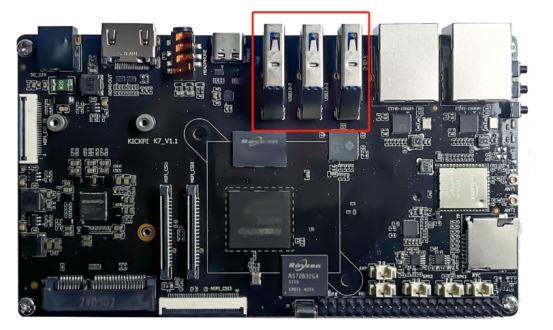
USB Type A (1 - 3)

The motherboard has three USB 3.0 TYPE - A interfaces, supporting HOST mode. They can be connected to common USB peripherals such as mice, keyboards, cameras, and docking stations.
USB Type C

The motherboard is equipped with one USB 3.0 TYPE - C interface with the following features:

  • Supports automatic mode recognition and switching.

  • Supports HOST mode, allowing connection to USB peripherals such as mice, keyboards, cameras, and docking stations.

  • Supports DEVICE mode, enabling functions such as adb.

  • Supports DP v1.4 display output.

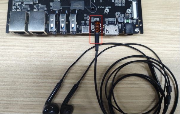
Headphone

The motherboard is equipped with one 3.5mm headphone jack.

Hardware Wiring
LCD

4G/5G

The motherboard is equipped with one MINI - PCIE interface, which can be connected to 4G/5G modules. The compatible modules are as follows:

Model
Wireless Support

EC20

4G

EC200

4G

RG200U

5G

Hardware Wiring

Wiring for connecting the motherboard to a 4G or 5G mobile network module via MINI-PCIE.

Inserting a SIM card into the motherboard.

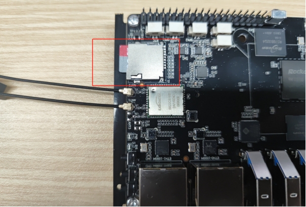
SD Card

The motherboard is equipped with one Micro SD Card interface, which can be connected to an SD memory card for file read and write operations.

Hardware Wiring
IR

The motherboard supports infrared remote control and is compatible with the KICKPI remote control by default.

KICKPI Remote Control

Infrared Remote Control Receiver

WIFI

An onboard 8822CS module is provided.

BT

An onboard 8822CS module is provided.

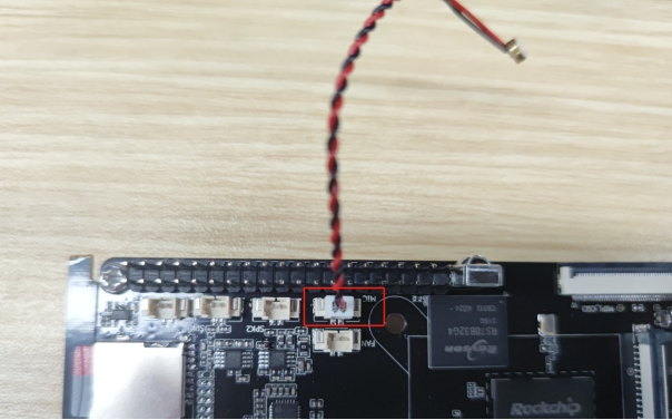
MIC

The motherboard is equipped with one MIC interface, which can be connected to a MIC microphone for recording.

Hardware Wiring
Speaker

The motherboard is equipped with two speaker interfaces, supporting audio output for left and right channel speakers.

Hardware Wiring

RTC

The motherboard has an onboard RTC module hym8563 and is equipped with one RTC battery interface. After connecting the battery, the RTC can continue to work using the battery when the motherboard loses power.

Hardware Wiring

Test steps:

  1. Connect the development board to the network to automatically synchronize the correct network time.

  2. Disconnect the network connection and the power supply of the development board.

  3. After waiting for some time, reconnect the power supply of the development board.

  4. If the system time is consistent with the current time, the RTC function is normal.

FAN

The motherboard is equipped with one fan interface. The fan is turned on by default after power-on.

Hardware Wiring
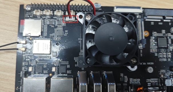
Switch Control

Turn on the fan

console$ echo 255 > /sys/class/leds/fan/brightness

Turn off the fan

console$ echo 0 > /sys/class/leds/fan/brightness

M.2 SSD

The motherboard is equipped with one PCIE 2.0 M.2 SSD hard drive interface, which can be connected to a hard drive for file read and write operations.

Hardware Wiring

MPP

H.265 HEVC Main10 L5.1 yuv444: 4K 120fps
H.264 AVC High10 L5.1 yuv422: 4K 60fps
H.264 MVC up to 1080P 60fps
VP9 Profile0/2 L5.1: 4K 120fps
AVS2 Profile0/2 L10.2.6: 4K 120fps
AV1 Main10 L5.3: 4K 120fps
4K@60fps video encoders for H.264/H.265

Debug Information

Enable debug information

$ export mpp_syslog_perror=1
$ echo 0x100 > /sys/module/rk_vcodec/parameters/mpp_dev_debug

After enabling debug information, there will be log information similar to the following when calling hardware encoding and decoding. [ 893.134037] rk_vcodec: 27b00100.rkvdec:0 session 3705:19 time: 1333 us hw 1312 us [ 893.167444] rk_vcodec: 27b00100.rkvdec:0 session 3705:19 time: 1381 us hw 1313 us [ 893.200503] rk_vcodec: 27b00100.rkvdec:0 session 3705:19 time: 1420 us hw 1313 us

Disable debug information

$ export mpp_syslog_perror=0
$ echo 0x100 > /sys/module/rk_vcodec/parameters/mpp_dev_debug

Debian / Ubuntu

Rockchip provides MPP-related tools for use.

Hardware Encoding Test

mpi_enc_test

usage: mpi_enc_test [options]
 -i       input_file          input frame file                       
 -o       output_file         output encoded bitstream file          
 -w       width               the width of input picture             
 -h       height              the height of input picture            
 -hstride hor_stride          the horizontal stride of input picture 
 -vstride ver_stride          the vertical stride of input picture   
 -f       format              the format of input picture            
 -t       type                output stream coding type              
 -tsrc    source type         input file source coding type          
 -n       max frame number    max encoding frame number              
 -g       gop reference mode  gop_mode:gop_len:vi_len                
 -rc      rate control mode   set rc_mode, 0:vbr 1:cbr 2:fixqp 3:avbr
 -bps     bps target:min:max  set tareget:min:max bps                
 -fps     in/output fps       set input and output frame rate        
 -qc      quality control     set qp_init:min:max:min_i:max_i        
 -fqc     frm quality control set fqp min_i:max_i:min_p:max_p        
 -s       instance_nb         number of instances                    
 -v       trace option        q - quiet f - show fps                 
 -l       loop count          loop encoding times for each frame     
 -ini     ini file            encoder extra ini config file          
 -slt     slt file            slt verify data file                   
 -sm      scene mode          scene_mode, 0:default 1:ipc 
  • Encoding test for 100 frames of H.264 4096x2160

$ mpi_enc_test -w 4096 -h 2160 -t 7 -o ./test.h264 -n 100

View the results

$ tail -f /var/log/syslog

kickpi mpp[3557]: mpi_enc_test: chn 0 encode 100 frames time 3763 ms delay 27 ms fps 26.57 bps 10605252

  • Encoding test for 100 frames of H.265 4096x2160

$ mpi_enc_test -w 4096 -h 2160 -t 16777220 -o ./test.h265 -n 100

View the results

$ tail -f /var/log/syslog

kickpi mpp[3560]: mpi_enc_test: chn 0 encode 100 frames time 4086 ms delay 36 ms fps 24.47 bps 19594276

Hardware Decoding Test

mpi_dec_test

 usage: mpi_dec_test [options]
 -i       input_file   input bitstream file                                 
 -o       output_file  output decoded frame file                             
 -w       width        the width of input bitstream                          
 -h       height       the height of input bitstream                         
 -t       type         input stream coding type                              
 -f       format       output frame format type                              
 -n       frame_number max output frame number                               
 -s       instance_nb  number of instances                                   
 -v       trace option q - quiet f - show fps                                
 -slt     slt file     slt verify data file                                 
 -help    help         show help                                             
 -bufmode buffer mode  hi - half internal (default) i -internal e - external
  • Decoding test for 100 frames of H.264 4096x2160

$ mpi_dec_test -t 7 -i test.h264 -n 100

View the results

$ tail -f /var/log/syslog

kickpi mpp[3564]: mpi_dec_test: decode 100 frames time 596 ms delay 25 ms fps 167.53

  • Decoding test for 100 frames of H.265 4096x2160

$ mpi_dec_test -t 16777220 -i test.h265 -n 100

View the results

$ tail -f /var/log/syslog

kickpi mpp[3569]: mpi_dec_test: decode 100 frames time 803 ms delay 49 ms fps 124.47

Chromium Video Test

Connect the board to a display device, open a virtual terminal or a debug serial terminal, and execute the following command to start the Chromium video test.

$ source /rockchip-test/chromium/test_chromium_with_video.sh

There is a compatibility issue with hardware decoding configuration between Rockchip Chromium and GStreamer in Ubuntu!

Chromium is configured for use by default. If Chromium does not call hardware decoding, use the following command to fix it.

$ source /rockchip-test/chromium/chromium_mpp_fix.sh

After configuration, Chromium can call hardware decoding by default.

GStreamer Video Test

sudo GST_DEBUG=2 gst-launch-1.0 playbin uri=file:///usr/local/test.mp4 video-sink="autovideosink" audio-sink=fakesink

If there are signs of MPP calls, it means the hardware decoding is successfully called.

There is a compatibility issue with hardware decoding configuration between Rockchip Chromium and GStreamer in Ubuntu!

Chromium is configured for use by default. If you need GStreamer to call hardware decoding, use the following command to fix it.

$ source /rockchip-test/gstreamer/gstreamer_mpp_fix.sh

This command requires an internet connection to ensure 'apt update' succeeds.

After configuration, GStreamer can call hardware decoding by default.

NPU

6 TOPS*@INT8
Support int4/int8/int16/FP16/BF16/TF32
Support deep learning frameworks: TensorFlow, Caffe, Tflite, Pytorch, Onnx NN, Android NN, etc

Debian / Ubuntu

Rockchip provides NPU test scripts.

# ls /rockchip-test/npu2
model  npu_freq_scaling.sh  npu_stress_test.sh  npu_test.sh

NPU frequency test script npu_freq_scaling.sh

usage()
{
    echo "Usage: npu_freq_scaling.sh [test_second] [every_freq_stay_second]"
    echo "example: ./npu_freq_scaling.sh 3600 30"
    echo "means npu_freq_scaling.sh will run 1 hour and every cpu frequency stay 30s"
}

Example: Run the NPU with frequency changes for 60 seconds, changing the frequency every 10 seconds.

# ./npu_freq_scaling.sh 60 10
test will run 60 seconds
every npu frqeucny will stay 10 seconds
set ddr frequency to 700000000
set ddr frequency to 300000000
set ddr frequency to 700000000
set ddr frequency to 950000000
set ddr frequency to 500000000
set ddr frequency to 700000000
======TEST SUCCESSFUL, QUIT=====

NPU stress test script npu_stress_test.sh

# ./npu_stress_test.sh
rknn_api/rknnrt version: 2.0.0b0 (35a6907d79@2024-03-24T10:31:14), driver version: 0.9.7
model input num: 1, output num: 1
input tensors:
  index=0, name=input, n_dims=4, dims=[1, 224, 224, 3], n_elems=150528, size=150528, fmt=NHWC, type=INT8, qnt_type=AFFINE, zp=0, scale=0.007812
output tensors:
  index=0, name=MobilenetV1/Predictions/Reshape_1, n_dims=2, dims=[1, 1001, 0, 0], n_elems=1001, size=2002, fmt=UNDEFINED, type=FP16, qnt_type=AFFINE, zp=0, scale=1.000000
custom string: 
Begin perf ...
   0: Elapse Time = 2.85ms, FPS = 351.12
   1: Elapse Time = 2.70ms, FPS = 370.37
   2: Elapse Time = 2.59ms, FPS = 386.85
   3: Elapse Time = 2.69ms, FPS = 371.61
   4: Elapse Time = 2.62ms, FPS = 381.97
   5: Elapse Time = 2.61ms, FPS = 383.44
   6: Elapse Time = 2.58ms, FPS = 387.75
   7: Elapse Time = 2.70ms, FPS = 370.51
   8: Elapse Time = 2.64ms, FPS = 378.36
   9: Elapse Time = 2.68ms, FPS = 372.44
---- Top5 ----
0.935059 - 156
0.057037 - 155
0.003881 - 205
0.003119 - 284
0.000172 - 285

The content after Begin perf... shows the performance data of multiple model runs:

  • Each record shows the run number, the corresponding elapsed time (Elapse Time), and the frames per second (FPS). For example, 0: Elapse Time = 2.85ms, FPS = 351.12 means that during the first model inference run, it took a total of 2.85 milliseconds, and from this, it can be calculated that 351.12 frames of data can be processed per second (the FPS is calculated by dividing 1000 by the elapsed time for each run, and then converting the unit to frames per second).

The ---- Top5 ---- section presents the top 5 categories with the highest probabilities in the model inference output results, along with their corresponding probability values and category numbers:

  • 0.935059 - 156 means that the model believes the input data (such as an image) is most likely to belong to category number 156, with a corresponding probability as high as 0.935059. This relatively high probability value indicates that the model has a relatively high confidence in this judgment.

  • The subsequent 0.057037 - 155, 0.003881 - 205, 0.003119 - 284, and 0.000172 - 285 list the category numbers and probability values of the second to fifth most probable categories respectively. These probability values decrease successively, indicating that the model's confidence in their belonging to the corresponding categories also gradually decreases.

GPU

Check GPU Utilization

console$ cat /sys/devices/platform/*gpu/utilisation

Example: Check the utilization in real-time

$ watch -n 1 'cat /sys/devices/platform/*gpu/utilisation'

Move the mouse or drag the window to check the GPU utilization to determine if hardware acceleration is working.

GLmark2 Performance Test

Rockchip provides GPU test scripts.

console$ ls /rockchip-test/gpu
gpu_test.sh  test_fullscreen_glmark2.sh  test_normal_glmark2.sh test_offscreen_glmark2.sh  test_stress_glmark2.sh
K7-loader
K7-RESET
image-20250409115024353
image-20250409115150900
K7-ETH
K7-TYPE A
K7-TYPE C
image-20250110152818915

See for details.

image-20250110152808407
image-20250421110846476
image-20250110152735195
K7-IR Remote
K7-IR
K7-8822CS
K7-8822CS
image-20250110152824237
image-20250110152830177
image-20250110153056417
image-20250110153117263
image-20250110153138855
Quick Start